FAQ
We will answer your question on the following pages.
About Resistance Welding
What is the important condition for resistance welding?
Resistance welding mainly depends on the following five conditions:
- Current
- Weld time
- Weld force
- Electrode (Current density)
- Heat balance
Resistance welding is to cause current to generate heat to weld; therefore, the magnitude of current, weld time, and current density are important factors. Weld force is also important.
What sort of setting is required for welding transformer?
The magnitude of weld time (cycles) and current (Amperes).
How is the good or no-good judgment conducted?
It depends on what is required. Tensile strength test and peel test measure weld strength and nugget size; additionally, cross section is observed. Our Weld Checker is useful for quality control.
Resistance welding usually forms molten material at welding points in order to join two metal sheets. What does micro-resistance welding create at the faying surface?
A. Heat is generated by the welding current due to the intrinsic resistance and the contact resistance alone. However, welding mechanisms are categorized into three types depending upon the materials of the workpieces.
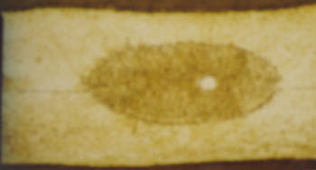
The joining of iron, iron alloy, or aluminum workpieces by the micro-resistance welding forms spots of cooled molten material (nuggets) at the faying surface, as is the case with normal resistance welding. Thin and flat nuggets are formed on both sides of the interfacing surface.
[A nugget formed by melt welding]
(80-μm thick SUS304 sheets are joined, and a piece of tungsten of 10 μm in diameter is folded.)
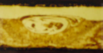
Copper sheets are bonded together immediately before melting, and are joined by diffusion. No nuggets are observed under an optical microscope. This welding increases temperature until a molten state is formed.
[Welding of a 0.3-mm thick copper sheet and a 0.5-mm nickel-plated iron sheet]
(No alloy layer is observed at the faying surface, although a plated layer is observed.)

Copper sheets are bonded together immediately before melting, and are joined by diffusion. No nuggets are observed under an optical microscope. This welding increases temperature until a molten state is formed.
[Welding of a 0.1-mm thick nickel sheet and a 0.22-mm nickel-plated iron sheet]
(Nickel is trapped in the iron sheet due to a plastic flow.)
What is the excellent feature of inverter welding power supply?
The following three:
- High thermal efficiency and short weld time ensure clean and neat welding.
A single-phase ac current comes to zero periodically, resulting in intermittent heat supply. An inverter power supply flows current which is never to be zero, ensuring continuous heat supply. Owing to this, welding is performed in a short period of time and nugget receives less thermal effect. Consequently, clean and neat weld is obtained. - Spatter is reduced; stable welding is conducted.
Weld time and rise time of weld current are adjustable, corresponding to material and shape of metal. Weld condition setting not to generate spatter is possible. - Small-sized, light-weighted welding transformer is easy to mount on automated machine.
Compared with other welding power supply, welding transformer is small sized.
Advise us of the feature of capacitor welding power supply.
Capacitor welding power supply charges a capacitor once, then discharges to flow a large current at a time. Owing to the large current, it can weld high-thermal-conductivity material such as aluminum, copper. As it charges capacitor, input capacity of power supply can be reduced; nevertheless, a stable welding is performed.
However, current rises steeply and gradient angle of the rising current cannot be controlled, causing a spatter easily. Electrode force must be increased to reduce the spatter. Precaution against Peltier effect which is due to direct current is needed.
What is the excellent feature of transistor welding power supply?
Transistor welding power supply does not need a welding transformer, but performs high-speed control of welding current directly by means of transistor; so it reduces spatter, ensuring ultra-precision welding. This power supply is suited for welding such as fine wire, cross wire, high-resistance material; also suitable for welding micro-electronic parts such as metal foil, contact, battery tab.
What is toroidal coil?
It is called Rogowskii coil having an air-cored coil. It detects magnetic field generated by current, and measures current intensity.
This coil is hung on secondary conductor, through which secondary current flows, to use. It is combined with our Weld Checker for weld quality control.
What is Peltier effect?
When dc current flows through two different kinds of metal which contact each other, temperature difference is generated between positive pole and negative one. This is called Peltier effect. Though this effect is applied to equipment in which cooling and heat radiation are repeated, uneven wear of electrode and irregular nuggets are unfavorably generated in welding.
As this effect occurs when current flows constantly in one direction, an ac power supply or polarity-switching power supply solves this problem.
For more detail, inquire us at:
sales@miyachi.com
Why do we have to grind an electrode periodically?
While it has been used, oxidized film forms at a tip of the electrode to generate heat; meanwhile it comes to be unable to weld. Also, melted coating of wire and debris of workpiece may stick to the electrode. Since such a foreign matter causes defective weld, electrode must be ground to remove them every certain number of welds periodically, corresponding to welding conditions. Furthermore, grinding the electrode is needed to shape up its tip because contact area increases to change current density.
What is projection welding?
It is to weld such a workpiece that is comprised of plates of which thicknesses are different remarkably. The thicker workpiece is provided with projection to increase current density; then Joule heat concentrates on the projection to weld.
[Advantage]
1. Simultaneous multi-point welding is possible. 2. As a flat electrode can be used, lifetime of the electrode is extended. 3. Thicker plate which is 3 times or more as thick as the other one can be welded to a certain extent. 4. If welded at two or more projections, the welds can endure more rotating torque. 5. Maintenance of electrode is easy. 6. Weld time is shorter. 7. Concentrated current results in energy saving.
[Disadvantage]
1. Multipoint welding causes welding facility to be larger (current capacity, weld force). 2. Projections must be leveled. 3. Electrodes must be maintained in parallel severely.
Advise us of the difference between secondary-constant-current control, and power-supply-voltage fluctuation-compensating control.
We will explain this control on our ac power supply MEA-100A.
[Power-supply-voltage fluctuation-compensating control]
工In a factory, power-supply voltage fluctuates frequently, affecting welding. This control applies constant current even though power supply voltage fluctuates. As compensated current flows for the first half cycle, welding current applied even for a short period of time such as a half cycle, one cycle, ensures stable welding.
[Secondary-constant-current control]
Secondary current of welding transformer is fed via toroidal coil back to controller in order to be kept constant. It is the feature that a constant current flows even when resistance of workpiece changes. In power- supply-voltage fluctuation-compensating control, current varies corresponding to the amount of workpiece that comes in throat of welding head in metal sheet welding; on the contrary, secondary-constant-current control flows a constant current.
Does welding transformer flow larger current through higher-voltage tap?
Welding transformer generates large current at low voltage. For example, it can deliver 10A at 200V or 200A at 10V, or 1000A at 2V (Energy are identical: 200V x 10A = 2000VA, 10V x 200A = 2000VA, 2V x 1000A = 2000VA). Theoretically, lower-voltage tap can flow a larger current; practically, however, current flows by Ohm's law: I (current) = E (voltage)/R (resistance) which shows that E is necessary to a certain extent to flow large current. Consequently, higher voltage tap can flow larger current for high-resistance workpiece.
What is the important element in fusing?
Fusing joint is not to utilize Joule heat generated in workpiece as in resistance welding, but to utilize Joule heat generated in electrode to remove coating of lead wire, joining lead to terminal through heat cohesion.
If resistance welding is conducted to this joint, terminal will melts down; therefore, adequate welding conditions must be decided to remove coating, causing cohesion of lead and terminal. Application of current is commonly done by 2-stage current application: the first stage WELD1 in which terminal is deformed (preliminary shaping), and the second stage WELD2 in which fusing is performed. If 1-stage current application is employed, preliminary shaping is to be done by up-slope current.
Advise us of condition setting of resistance welding.
We do not have definite method of condition setting because welding condition depends on such as material of workpiece, strength you need; however, you have to decide the welding conditions, adjusting weld time, welding current, and weld force since welding is related to the three.
[Weld lobe by 2.0kgf of weld force per two shots]
(Part to be welded: Ni t=0.1mm and Fe t=0.25mm, Welding method: 2 shots series welding, Space between shots: 3mm, Electrode: AL-60 Φ1.5mm, welder: Transistor-controlled welding power supply, Weld cable: 38sq. 1000Lmm.)
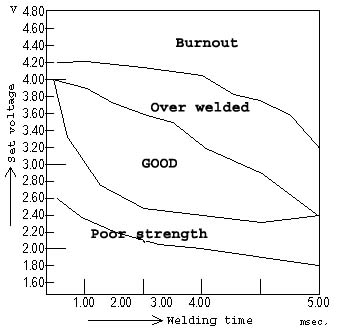
The procedure is as follows:
Set weld force to medium on weld force scale on weld head, set welding current and weld time relatively lower; then increase the conditions gradually while welding. On inverter power supply and ac power supply, set weld time a little bit shorter and increase only current. If the maximum current presents insufficient weld, increase weld time, then increase current from zero. Start with such settings that you cannot weld. When you come to weld slightly, continue your test welding while you observe whether spatter is generated.
Increase the weld force to reduce spatter. When tensile strength test and peel test result in sufficient and stable weld strength, you continue welding with these welding conditions.
If both maximum welding current setting and maximum weld time setting do not present sufficient strength, lower the weld force slightly for a trial; sometimes, weld strength increases. If welding is still insufficient, capacity of welding machine is not enough; you need a welding machine of next larger capacity.
On an ac welding power supply, try to decrease the number of cycles and raise heat setting and tap voltage if the power supply has an ample capacity; you may obtain a weld with less change of color.
For more detail, inquire us at:
sales@miyachi.com
Poor welds which is often happened and the preventive measures for them
| Welded condition | Current | Weld force | |
|---|---|---|---|
| Spatter | Down | Up | Make follow-up of electrodes better |
| Splash | Down | Up | Make follow-up of electrodes better |
| Blow hall | - | - | Make follow-up of electrodes better |
| Small nugget | Up | Down | - |
| Unequal nugget size | - | - | Control current density. Resolve the peltier effect. |
| Large dent | Down | Down | Use "R"-shaped electrodes |
What is heat effect?
It is the effect that is exerted to workpiece by heat generated in welding. The workpiece may change in color, discolor, deform, or may be breakable; parts may be degraded.
To reduce the heat effect, heat must be applied to workpiece effectively and welding must be conducted in a short duration of time. Inverter or transistor welding power supply is another choice.
Is 2-stage welding necessary? What is the effect of it?
It is effective to weld plated metal. The plating metal is removed in the first stage, pushed off electrode and cooled in COOL; then, workpiece is welded in the second stage. Projection welding, however, basically employs one-stage welding.
What kind of countermeasure do you have to weld workpieces of different thickness?
Provide thicker metal sheet with projection; however, if this sheet is 3 or more times thicker than thinner one, you will have difficulty in welding them.
What should we consider, including weld conditions, before introducing a new micro-resistance welding system for the first time?
First, you should consider whether the metal materials can make a firm alloy by melting together or whether they can be joined by diffusion. Some combinations of metal materials will always be weak. In this case, you will have to consider using other materials, or using an insert metal that easily coalesces with both workpiece metals to form a diffusion bonding.
Second, consider the workpiece shapes at welding points. In order to use resistance welding, workpieces have to be processed into shapes that allow a constant force and current to be applied. Also, welding increases the temperature of both metals to their melting points, so their heat capacities (masses) at the surface of the welding point have to be balanced. In addition, you have to pay attention to the selection of a plating material.
Third, consider workpiece configuration. You cannot micro-resistance weld together workpieces that are usually soldered without changing the materials or shapes used. Workpieces that have been soldered are designed to be soldered; workpieces have to be designed to be resistance-welded in order for a resistance welding system to be used. To obtain micro-resistance weld conditions with wide margins, workpiece design is very important, in fact vital, because the bottom-line goal is to maintain stable welding qualities.
Finally, determine the configuration and materials of the workpieces, and at the same time, determine the method of applying current, or the paths via apply current or force are applied. Usually, three types of applying current are used: direct, indirect, and series methods which are also used in resistance welding. The parallel-gap method, similar to the series method, is specifically used in micro-resistance welding. It does not weld two spots; instead it welds a spot between the electrodes.
About Laser Welding
What is the feature of YAG laser?
YAG laser is generated when a YAG (yttrium-aluminum-garnet) crystal is excited. A YAG crystal is regarded as one of the most excellent one because it shows various oscillation forms and also presents excellent optical characteristics.
- Transmittable through an optical fiber.
The YAG laser light is transmitted using optical fibers, resulting in easy remote processing and simplified system.
The laser can be set up easily in factory automated system. A single unit offers simultaneous multipoint welding (power-sharing delivery welding) and time-scheduled welding (time-sharing delivery welding) At present, no optical fiber can transmit a high-power CO2 laser light for laser processing.
- Invisible light.
Laser light is near infrared light of 1064 nanometer (1.064 micrometer) wavelength; it is invisible.
- Suitable for micro-processing.
The YAG laser does not diverge but proceeds straight. As the wavelength (1.06μm) is one tenth of CO2 laser wavelength (10.6μm), the YAG laser can be focused to a fine beam, leading to micro-processing.
What is the feature of laser welding?
The features of the laser welding are:
Not only metal but also plastic can be laser welded.
- Ultra-precision processing.
- Less deformation of workpiece owing to non-contact processing.
- No electrode is required unlike resistance welding.
- Capable of welding different metals, and also non-conductive materials.
- No heat distortion owing to short period of joining time.
When an optical fiber is replaced with a finer fiber under the same conditions, beam is more focused. Is the density of power increased?
Yes, power density increases. If energy is constant, the smaller the projection area is, the higher the density is; however, you must use caution in the fact that only smaller amount of laser energy can be inputted to smaller area of the end of fiber.
About Laser Marking
What is laser marking?
Laser marking is a process to mark materials using a fine spot diameter laser beam and is widely used for putting marks such as brand names, best-before-date, serial numbers on a variety of materials.
What are the major marking methods like?
Major marking methods are as follows:
- Laser marking
Irradiate a laser beam on a material to change and color it. Marking contents can be easily changed using a software. Clear fine marking even on tiny parts is possible.
- Inkjet printing
Shoots a jet of micro-particles of ink to mark with dots. An inkjet printer used with a personal computer, and a printer for industrial-use to mark best-before-date on laminated film are the major applications.
- Ink stamping
Presses ink-supplied relief or intaglio onto an object to mark. This is the most popular method from the past. Though the equipment is less expensive, production routine cost is relatively high; additionally, it requires to control ink.
- Punching
Presses a numbering head, on which desired marks such as letter, character are engraved, onto an object. This is widely accepted for marking on metal. While the mark is very reliable and ever-lasting, this method is less productive and needs much time to change the head.
What is the advantage of laser marker like?
It is as follows:
- Environmentally friendly and easy recycling.
Unlike the marking with ink, no solvent is required. Since no ink sticks to base material, it is recycled easily. Also manufacturing process is reduced remarkably.
- Marking not erasable
Since the laser beam changes a material itself, the mark is never erased, unlike an ink-using method. This marking complies with quality control requirements in PL Laws and ISO International Standard.
- Micro-marking
Lasers are capable of fine marking which inkjet marking can never perform. It is the best suitable choice for microelectronic parts.
- Easy to design and change marking contents
The marking software is easy to use, so can design marks easily and can switch to other marks easily at your PC. Laser markers are suitable even for a small-volume production of diversified products.
- Productivity-improving and labor-saving
The high-speed marking contributes to improvement in productivity. The relatively easy maintenance saves labor. Production line can be easily automated and operates unmanned in the nighttime.
- Wide range of laser-markable materials.
Various materials such as metal, resin, ceramics, semiconductors, paper, glass are acceptable; in addition, laser marking also accepts material with oil film in which inkjet printing has difficulties.
We would like to operate the laser marker.
You can operate it at our application laboratory in our Noda, Nagoya and Osaka Sales Offices. Also, we can visit you and hold a demonstration at your site.
For more detail, send an e-mail to:
sales@miyachi.com
We will return an answer.